
miller welder manual
Safety Precautions
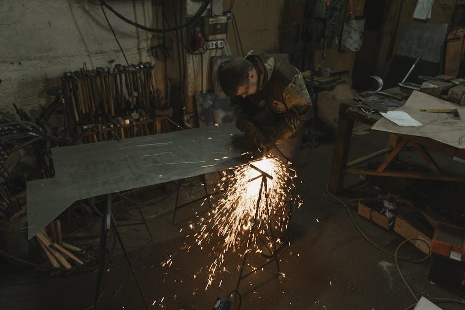
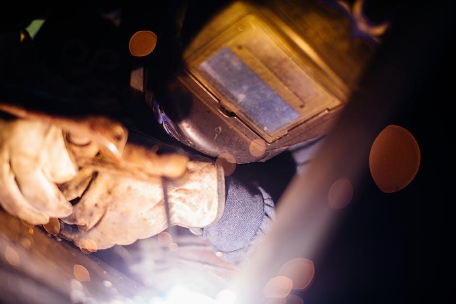
Always wear protective gear, including welding helmets, gloves, and safety glasses, to prevent eye and skin damage from sparks and UV radiation.
- Ensure proper ventilation in the workspace to avoid inhaling harmful welding fumes.
- Keep flammable materials away from the welding area to reduce fire hazards.
- Disconnect power before performing maintenance or repairs to avoid electrical shocks.
- Never touch electrical components with wet hands or while standing on a conductive surface.
Regularly inspect welding cables and equipment for damage to ensure safe operation.
1.1 General Safety Guidelines
Adhere to all safety guidelines to minimize risks while operating Miller welders. Always read the manual thoroughly before use.
- Wear proper PPE, including welding helmets, gloves, and safety glasses, to protect against sparks and UV radiation.
- Ensure the workspace is well-ventilated to avoid inhaling harmful fumes.
- Keep flammable materials away from the welding area to prevent fires.
- Inspect equipment regularly for damage or wear to ensure safe operation.
Never operate the welder near water or in damp conditions to avoid electrical shock. Follow all local safety regulations and guidelines.
1.2 Specific Hazards in Welding
Be aware of specific hazards when welding, such as electric shock, fire risks, and fume inhalation. Arc welding produces intense UV radiation, which can cause eye damage and skin burns.
- Prevent electric shock by avoiding contact with live electrical components.
- Keep the work area clear of flammable materials, as sparks can ignite fires.
- Welding fumes contain harmful chemicals like chromium and nickel, which can cause long-term health issues.
Always follow proper grounding and ventilation procedures to minimize these risks.
1.3 California Proposition 65 Warnings
Warning: Welding or cutting with this equipment produces fumes and gases containing chemicals known to the State of California to cause cancer, birth defects, or other reproductive harm. Engine exhaust from this product contains chemicals known to the State of California to cause cancer, birth defects, or other reproductive harm. Avoid inhaling fumes or gases; use proper ventilation and protective equipment.
- Exposure to welding fumes may cause serious health issues.
- Follow all safety guidelines to minimize health risks.
Installation and Setup
Place the welder on a stable, heat-resistant surface, ensuring good ventilation. Keep it away from flammable materials and ensure proper grounding for safety and optimal performance.
- Position the unit in a well-ventilated area to prevent fume accumulation.
- Ensure all connections are secure and meet local electrical codes.
2.1 Location and Placement of the Welder
Position the welder on a stable, heat-resistant surface in a well-ventilated area. Ensure it is placed away from flammable materials and combustible surfaces. The location should provide easy access for maintenance and operation while keeping the surrounding area clear of obstructions. Proper grounding is essential to prevent electrical hazards. Avoid installing near open flames or sparks to reduce fire risks. Keep the unit away from direct sunlight and moisture for optimal performance and longevity.
2.2 Weld Output Terminals and Cable Size Selection
Properly connect the weld output terminals to ensure safe and efficient operation. Select cable sizes based on the total circuit length and current requirements, as specified in the manual. Use the correct polarity for connections: positive terminal for work lead and negative for the electrode holder. Ensure cables are securely attached to avoid loose connections. Refer to the cable size chart to prevent overheating and maintain optimal welding performance. Always follow safety guidelines for electrical connections to minimize risks.
2.3 Input Power Connections
Connect the welder to a power source that matches its voltage and current requirements. Ensure all connections comply with local electrical codes and regulations. Use the appropriate gauge wire to handle the current load without overheating. Ground the equipment properly by connecting the grounding terminal to a reliable earth source. Always disconnect and lockout the power supply before servicing or adjusting the unit to prevent accidental start-ups and electrical hazards.
Operation
Familiarize yourself with the controls and ensure proper setup before starting. Select the appropriate welding process using the Process Control. Follow the starting procedures for TIG or Stick welding as outlined in the manual to ensure safe and effective operation.
3.1 Controls and Indicators
The Miller welder features a user-friendly control panel with clear indicators for operation. The Power On light illuminates when the unit is powered up, while the Process Control allows selection between Stick and TIG modes. The High Temperature Shutdown Light activates if the unit overheats, ensuring safe operation. Additional indicators provide status updates, and the Remote 14 receptacle enables optional remote control functionality for enhanced convenience during welding tasks.
- Power On Light: Indicates the welder is powered and ready for use.
- Process Control: Selects between Stick (SMAW) or TIG (GTAW) welding modes.
- High Temperature Shutdown Light: Alerts if the unit overheats, requiring a cooldown period.
3.2 Starting Procedures for TIG and Stick Welding
For TIG welding, ensure the workpiece is clean and properly grounded. Select DCEN mode, attach the TIG torch to the negative terminal, and the work lead to the positive terminal. Use the Lift-Arc start by touching the tungsten to the workpiece and lifting slightly to establish the arc. For Stick welding, choose DCEP mode, attach the electrode holder to the positive terminal, and use the scratch start technique to initiate the arc. Always ensure proper ventilation and follow safety guidelines.
- TIG Start: Use Lift-Arc method with DCEN configuration.
- Stick Start: Employ scratch start technique with DCEP setup.
Maintenance and Troubleshooting
Regularly inspect and clean welding cables and connections. Check for loose terminals and ensure proper cooling to prevent overheating. Replace damaged parts promptly to maintain performance.
4.1 Routine Maintenance Tasks
Perform daily inspections of welding cables and terminals for wear or damage. Clean the power source and torch regularly to prevent dust buildup. Check coolant levels and ensure proper airflow for optimal cooling. Schedule professional servicing every 500 hours of operation to maintain warranty and performance standards. Always refer to the manual for specific maintenance schedules and procedures.
4.2 Common Issues and Solutions
- No weld output: Check power connections and ensure the unit is turned on. Verify circuit breakers or fuses haven’t tripped.
- Poor arc starts: Ensure proper polarity settings and clean terminals. Replace worn-out or damaged welding cables.
- Overheating: Reduce duty cycle or operating amperage. Ensure adequate ventilation and clean cooling vents.
- Porosity in welds: Check shielding gas flow and ensure proper torch movement. Clean the weld area before starting.

Electrical Diagrams
Refer to Figure 7-1 for a detailed circuit diagram, outlining power source connections and components to ensure proper setup and operation of the welder.
5.1 Circuit Diagram Overview
The circuit diagram provides a detailed visual representation of the welder’s electrical connections and components. It illustrates the flow of electricity from the power source through the output terminals and control circuits. This diagram is essential for understanding the welder’s internal workings, identifying connections, and troubleshooting electrical issues. Refer to it for installing, maintaining, or repairing the unit to ensure safe and efficient operation. Always follow the diagram’s guidance for proper setup and functionality.
High-Frequency Welding
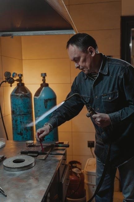
High-frequency welding uses a high-voltage, low-current spark to initiate the arc, stabilizing it for consistent welds. Ideal for TIG welding, it enables arc starting without physical contact, reducing contamination and improving precision.
6.1 Principles of High-Frequency Welding
High-frequency welding generates a high-voltage, low-current spark to initiate and stabilize the arc. This method eliminates physical contact between the tungsten electrode and the workpiece, reducing contamination. By creating a consistent arc, it enhances weld quality and precision, especially in TIG welding. The process involves ionizing the air gap, allowing the arc to form reliably. Proper installation and grounding are essential to ensure safe and effective high-frequency operation.
6.2 Correct Installation and Grounding
Ensure all metal objects and wiring in the welding zone are grounded using 12 AWG wire. Properly bond conduit joints to maintain electrical continuity. Ground the workpiece as required by local codes to prevent electrical hazards. Maintain a distance of 50 feet from high-frequency sources in non-metal buildings to avoid interference. Always follow safety guidelines for correct installation to ensure reliable high-frequency welding performance and operator safety.
Selecting and Preparing Tungsten Electrodes
- Choose tungsten electrodes based on welding type: DC or AC.
- Grind electrodes correctly to avoid contamination.
- Store electrodes properly to maintain quality.
7.1 Choosing the Right Tungsten for DC or AC Welding
Selecting the appropriate tungsten electrode is crucial for optimal welding performance. For DC welding, use pure or thoriated tungsten for better current-carrying capacity and longevity. AC welding typically requires pure tungsten to ensure a stable arc and prevent contamination. Always match the electrode type to your welding process for consistent results and extended electrode life. Refer to the Miller manual for specific recommendations.
- Pure tungsten is ideal for AC welding due to its stability and resistance to contamination.
- Thoriated tungsten is recommended for DC welding as it enhances arc performance and durability.
7.2 Preparing Tungsten Electrodes for Use
Properly prepare tungsten electrodes by grinding them to a sharp point using a diamond wheel grinder. Clean the electrode with a wire brush to remove impurities. For AC welding, ensure the tip is symmetrical. Store electrodes in a clean, dry place to prevent contamination. Always handle tungsten with clean, dry gloves to avoid introducing contaminants. Refer to the Miller manual for specific grinding techniques and safety precautions.
- Grind in a well-ventilated area to avoid inhaling dust.
- Avoid cross-contamination between different types of tungsten electrodes.
Guidelines for TIG Welding (GTAW)
Maintain a consistent torch angle and distance to ensure proper arc control. Use the correct shielding gas flow rate for optimal weld quality and penetration.
- Keep the arc focused on the joint to minimize heat input and distortion.
8.1 Positioning the Torch and Grinding Tungsten
Position the TIG torch at a 15-20° angle, maintaining consistent distance for stable arc control. Hold the torch steady to ensure precise weld placement.
- Grind the tungsten electrode to a sharp point for DC welding or a blunt tip for AC welding, using a dedicated grinder to prevent contamination.
- Use a ventilation system while grinding to avoid inhaling tungsten particles.
8.2 Torch Movement and Shielding Gas Tips
Move the torch smoothly and steadily to maintain consistent weld penetration and appearance. Use a slight side-to-side motion for wider beads. Proper shielding gas flow is critical to prevent porosity and contamination.
- Always keep the gas nozzle 1/4 inch above the workpiece for optimal coverage.
- Adjust the gas flow rate (typically 15-25 CFH) based on material thickness and weld position.
Where to Find Additional Resources
For detailed guides and troubleshooting, visit MillerWelds.com. Technical manuals and support are available through authorized distributors worldwide.
9.1 MillerWelds.com and Technical Manuals
Visit MillerWelds.com for comprehensive resources, including owner’s manuals, troubleshooting guides, and product specifications. Technical manuals provide detailed instructions on safety, operation, and maintenance. Additional materials, such as DVD tutorials and welding guides, are also available for download or purchase. This platform is your go-to source for optimizing your welding experience with Miller equipment.
9.2 Authorized Distributors and Support
For personalized assistance, contact Miller authorized distributors. They offer expert advice and genuine parts, ensuring optimal performance. Distributors provide training and troubleshooting support, helping you resolve issues quickly. Visit MillerWelds.com/support to locate a nearby distributor. Their extensive network guarantees reliable service, enhancing your welding operations with trusted expertise.